We offer online custom sheet metal bending services,Providing one-stop solution for cutting and bending. Over 40+ surface finish options,Rapid prototyping and delivery.Communication with professional engineers,Free DFM (Design for Manufacturability) assessment within 24 hours.
Drawing review and analysis.Verify product precision requirements, material specifications, and forming characteristics against drawings and customer requirements, and mark key dimensions requiring critical control,Sheet metal flat pattern calculation and process documentation
02
Raw material pretreatment
Cut the raw material into pre-forming blanks based on the unfolded dimensions confirmed from the drawings, and select the appropriate processing equipment.
Depending on production requirements, available blanking methods include laser cutting, CNC punching (turret punching), shearing, and die cutting.
03
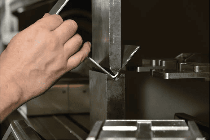
Custom Bending and Forming
Adjust the equipment based on sheet thickness, bending angle, and bending radius; complete all bending operations by following the principles of “inner before outer,” “small before large,” and “special before standard,” while performing repeated positioning for complex workpieces.
04
Assembly And Post-processing
Depending on product design specifications, assembly involves either welded or non-welded connections. Precision processing includes punching, tapping, ribbing, corner cutting, embossing, and laser marking, while uneven surfaces undergo grinding, brushing, and polishing.
05
Surface Finishes
We offer a variety of surface treatment solutions, allowing for the selection of the appropriate treatment based on the part’s application environment, as well as its wear and corrosion resistance requirements.
100% quality inspection,Videos,Photos,And dimensional reports can be provided before shipment,We offer customizable packaging services—including standard packaging—to ensure products arrive safely in the customer’s hands without damage during transit. We also provide end-to-end shipment tracking and door-to-door delivery options.
Sheet Metal Bending Process
There are various methods for sheet metal bending, and we can select the most suitable approach based on the specific part design. Some parts are best suited for CNC bending, while others are better processed using stamping dies. The following is a brief overview of these bending processes to help you choose the optimal solution for your project.
V-Bending
We achieve plastic deformation through a three-point contact established between the sheet metal and the tooling, relying on a V-shaped upper die to press the sheet into a lower die featuring a corresponding V-shaped groove.
Air Bending
It is a process in which a sheet is bent while in a “suspended state.”The bending angle can be changed by adjusting the downward pressing depth of the upper die.
Bottoming
It is a process in which the sheet material is fully compacted against the bottom of the lower die.
Coining
It is a high-precision, extreme-performance process that utilizes extremely high tonnage to bend metal sheets, achieving virtually zero springback.
U-bending
Continuously bend sheet material into arc or cylindrical structures by applying progressive pressure using rollers.
Rotary Bending
The sheet material is formed by being pulled around a mandrel using a rotating mold.
Step Bending
A large-radius circular arc structure is formed by joining together multiple consecutive, small-angle bends.
Design Guidelines for Regular Custom Sheet Metal Bending
(h:Bending height ;R:Internal bend radius;Plate thickness;B:Distance from the side of the bending punch to the pressing centerline;K :90° single-blade bend.)
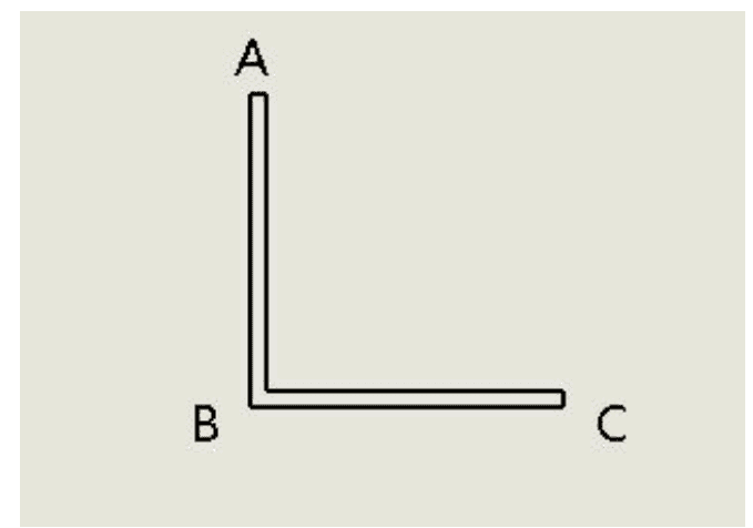
V-Bending-90° L-shaped right-angle bend
V-grooving bottom die + upper bending blade
Bending straight flange height:h≥R+2t
Hole edge to bend center:L≥2t
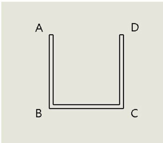
U-Bending-Two 90° V-bending operations or U-shaped forming die
Side vertical edge height:h≥R+2t
Hole edge to bend line:t<2mm:L≥R+t;t≥2mm:L≥R+2t
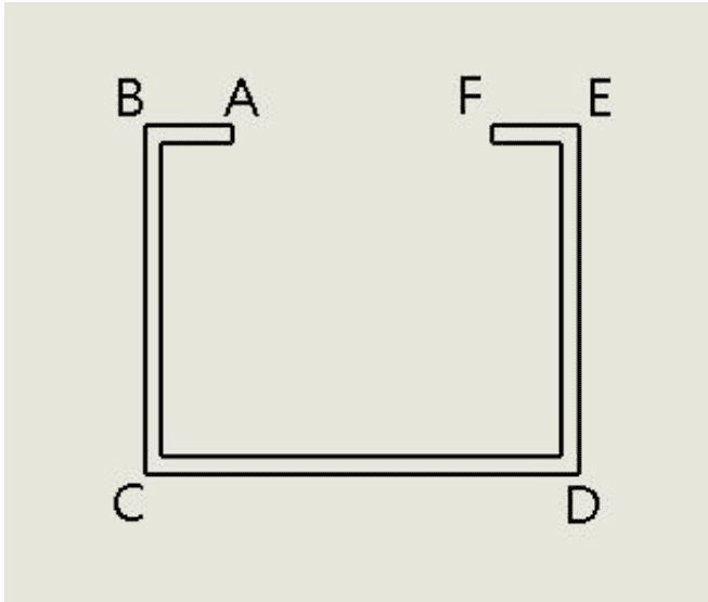
Flanged U-bending–
U-shaped bottom groove width:L min((U-groove bottom width)>B+2H+t;Total developed length of the U-shaped part:Ltotal=LAB+LBC+LCD+LDE+LEF+LFA-4K
Small flanges at both ends:Lmin≥3.5t+R
Frequently Asked Questions
First, please send us your 2D/3D drawings or samples, and confirm details such as quantity, material, and surface finish. Our team of professional engineers will evaluate the project and provide a quote. Once the price is mutually agreed upon, we will proceed with rapid prototyping; following sample approval, a mass production order can be placed.
We accept various payment methods, including credit/debit cards, PayPal, and bank transfers,30% deposit,100% balance before shipping
We recommend using a narrow V-groove of size 6 or larger for bending and setting appropriate minimum bend flange dimensions—for instance, recommending a flange larger than 3.5 mm for 1.0 mm thick sheet metal and larger than 5 mm for 1.5 mm thick sheet metal. Minimizing the use of narrow grooves helps reduce the likelihood of indentation marks on sheet metal parts at the design stage.
We usually only need 7–10 business days to finish the mold,Then send some samples to you for confirmation before the mass production
Yes, We update production progress weekly and provide dimensional reports, photos, or videos prior to shipment.
Yes, All documents are handled confidentially, and confidentiality agreements can be signed.